Building a 30 key keyboard
Oct 8, 2017A while back I realised I was a bit obsessed with mechanical keyboards, and I really wanted to build one. And almost as soon as I had ordered a 60% kit from mechboards.co.uk I was looking at 40percent.club and thinking about making a much smaller one too, from scratch.
I’ve been using mechanical keyboards on and off for about 20 years now, (mainly a cherry slimline board with ML switches which I’ve had for ages), but it was the sudden proliferation of fully-hipster keyboards at work, where everyone suddenly started getting code keyboards and things that made me start thinking about upgrading. There’s a very active and friendly seeming community (on reddit and geekhack and Deskthority) and I quickly settled on DIY.
People making DIY keyboards seem to be expected to post a “build log”, including a load of images of how things went at every step. These logs are really useful when it comes to building your own boards, and are a great way to get a feel for how to build a keyboard. I’ll post my own build logs of my 60% build in another post, but this post is about building a smaller board. A 30 key Gherkin board!
The gherkin keyboard
Gherkin keyboards are a project from 40percent.club. They’re tiny 30 key boards, which are powered by small and cheap Arduino Pro Micros (or clones) and take standard MX switches.
The site is full of lovely pictures but I found it a bit terse, especially since I had never built a fully-DIY keyboard before.
I started by ordering PCBs from EasyEDA following the author’s instructions, then I ordered the other bits from Amazon and RS components. I ordered switches from Optic Boards, where I got some Kailh Speed switches purely because they were a good price.
Laying out the boards
During my first build I overlooked the small cut on the right of the PCBs and ended up with the top plate on backwards. This is purely cosmetic but might cause problems with some sorts of USB cable.
To avoid this problem, make sure the cuts are on the right hand side, and if you push the switches through the top plate at the start of your build put the LED holes on the top of the switches.

The gherkin top plate.
Getting started
Building a keyboard is pretty easy if you’ve soldered before and have a decent iron with a small tip. The hardest thing to solder is the SMD MOSFET, which is tiny and must be properly oriented. In my first build I hand-soldered this component in the second I used a frying pan to cook it into position, which works really well.
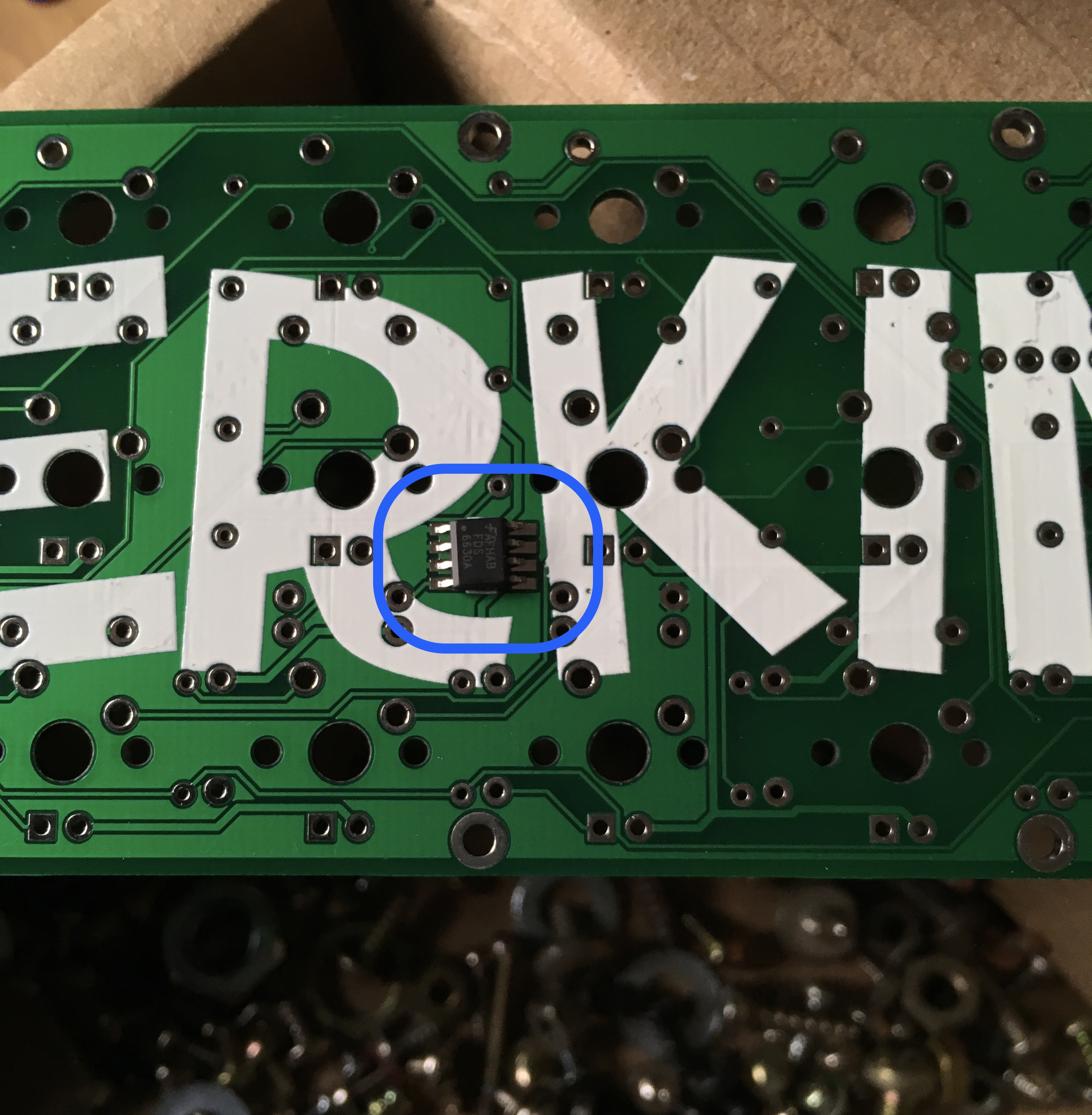
The FET before soldering, correctly oriented.
Once the MOSFET in place you can fit the diodes and resistors onto the top of the board. Watch out for the 100k resistor near the FET, its the only one with that value.
Soldering the board.
With the top done (which will take a while!) it’s time to think about the bottom.
The main issue here is deciding what to do with the Arduino Micro. I used a socket in my first build, but wired it directly in on the second, which made the build thinner over all but was much more fiddly.
If you’re using a socket, now is the time to solder it in place, as you’ll need to access the top of the board to do this, so you won’t want the switches in the way. See this post for some useful info on how to socket the pro micro. If you’re not using a socket you might want to add wires now, by pushing them through the holes in the micro and soldering them to the top of the board (but leaving them disconnected from the micro as you’ll need to remove it to solder the switches and LEDs).
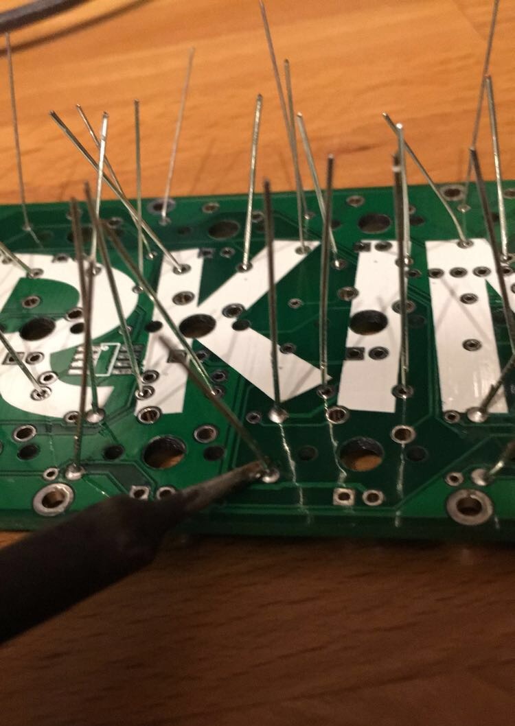
After installing the Micro you can move onto the switches, which should be relatively easy to install. Start by pushing them through the top plate (with the plate and switches correctly oriented as mentioned earlier), then just make sure none of the legs are bent underneath. Push the contacts through the PCB, then solder the switches at the corners to hold everything in place before moving onto the others. Then, it’s LED time.
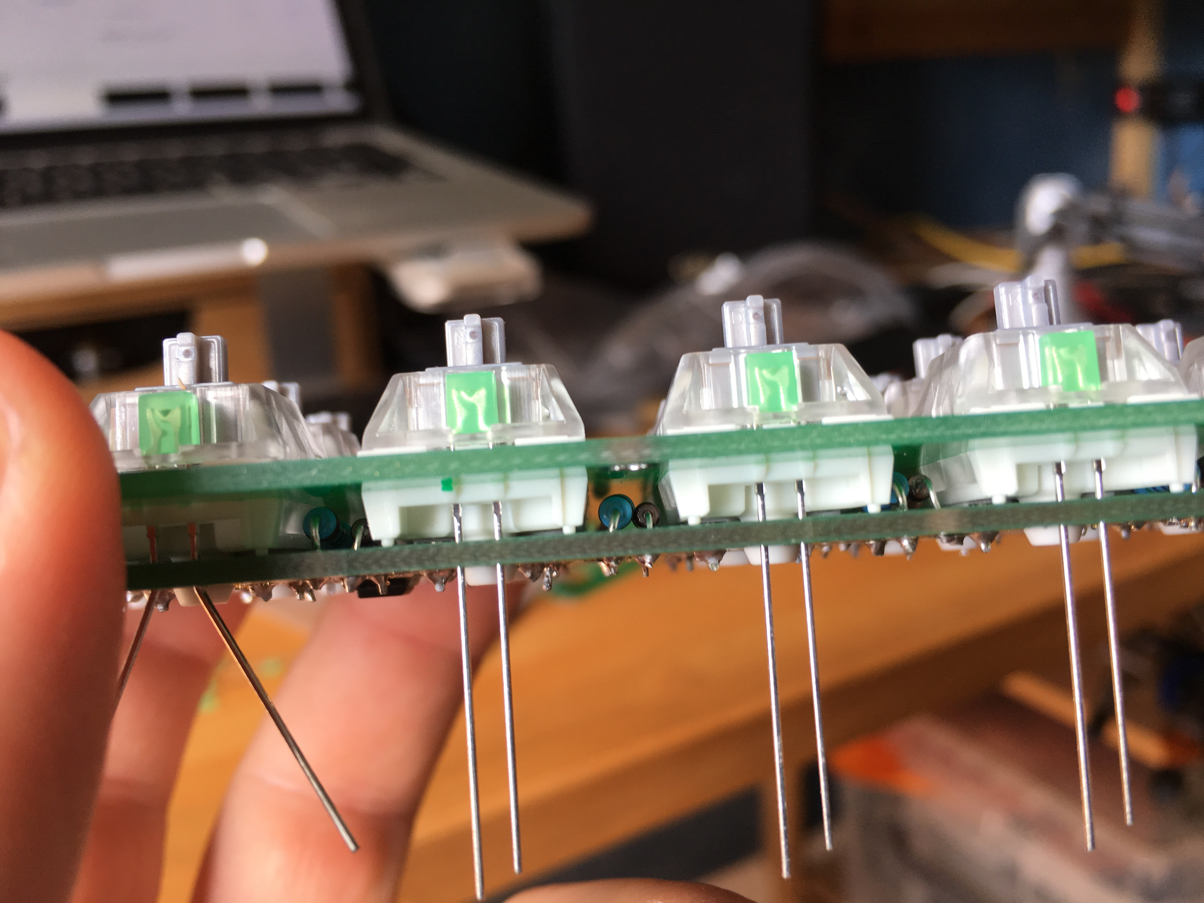
Ready to add the LEDs
When you’re soldering the LEDs, make sure you get the polarity correct otherwise they won’t work. Finally, once everything is in place you can think about flashing some firmware and running some tests!
Firmware
Before you can do anything else – like check all the LEDs and switches are working properly – you need some firmware. To flash firmware you need to ‘reset’ the Micro, by shorting two of the broken out pins on the board. This enables the Arduino bootloader, which lets you write code to the board. See the assembly page for more info.
40percent.club has instruction on easily creating firmware for the gherkin using an online tool, and includes a sadly incomplete config file to help you quickly create firmware (there are layers missing). This is great for testing, but if you want to have a fully usable keyboard you’ll need to do more.
I decided to go the whole hog and build my own firmware using the author’s own github repo.
To do this, I needed to get avr-gcc, which I did using homebrew, following
the instructions here:
GitHub - osx-cross/homebrew-avr: Homebrew AVR Toolchain.
Then I cloned https://github.com/di0ib/tmk_keyboard. And ran make in the
keyboard/gherkin directory. The built me a hex file ready for flashing onto
the pro micro.
With that done, I then needed to work out how to program the pro micro, which
was super-easy. Just short the RST and GND pins for a second (or less), then
use avrdude (which again I installed using homebrew).
The command I ended up using was:
avrdude -patmega32u4 -cavr109 -b57600 -Uflash:w:gherkin.hex -P/dev/tty.usbmodem1411
But you might find your tty device has a different name than mine did. Note
that you can probably use the makefile in the tmk repo to do this, see
tmk_keyboard/build.md at master · di0ib/tmk_keyboard · GitHub
for info.
You might also notice that there’s no cmd or meta button on the gherkin by
default, so you might want to add one to the firmware before building it –
I’ve no looked into this, so can’t include instructions.
Testing!
Once you have installed the firmware, you’ll want to check the LEDs and switches are all working. You can test the switches by just typing, or by using a tool like the keyboardtester. If any don’t work it’s likely that the legs are folded under the switch instead of going through the board. I fixed this sort of problem using a thin knife to gently push things back into place, but it’s much easier to prevent this than cure it.
If you want to look at symbols and function keys, and are using the default layout, you’ll need something like this to show you the layout. To toggle between layers you need to hold the corresponding button on the bottom row.
To test the LEDs you’ll need to toggle the backlight as it won’t be on by default. If you used the default layout, you can do this by holding the ‘B’ key and pressing the middle right key a few times. You should then find that everything lights up. If any LEDs fail to illuminate you probably have them backwards, so desolder and flip them, then check them again.
Final assembly
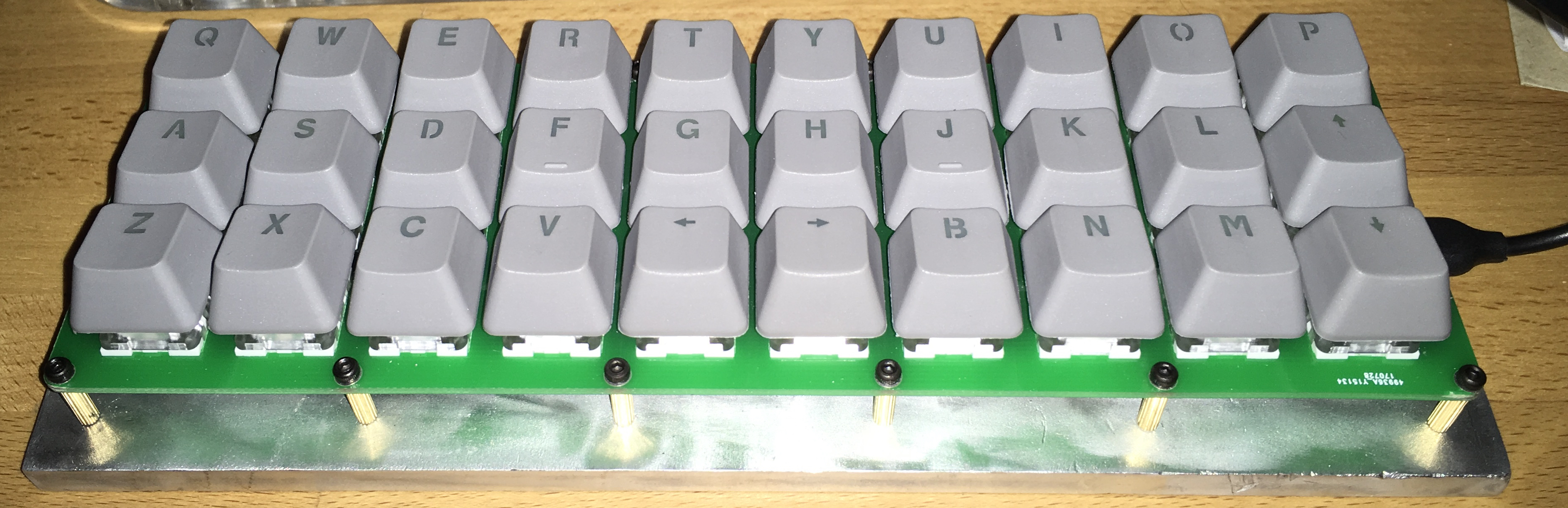
To finally build the thing just screw stand-offs through the top plate and onto the bottom, or if you’re feeling more adventurous you could build a custom bottom plate like I did, using metal.
I found a sheet of aluminium which I drilled and tapped in order to add a bit of heft. The result, which I’m really pleased with, looks like this:
Gherkin with metal base Gherkin with metal base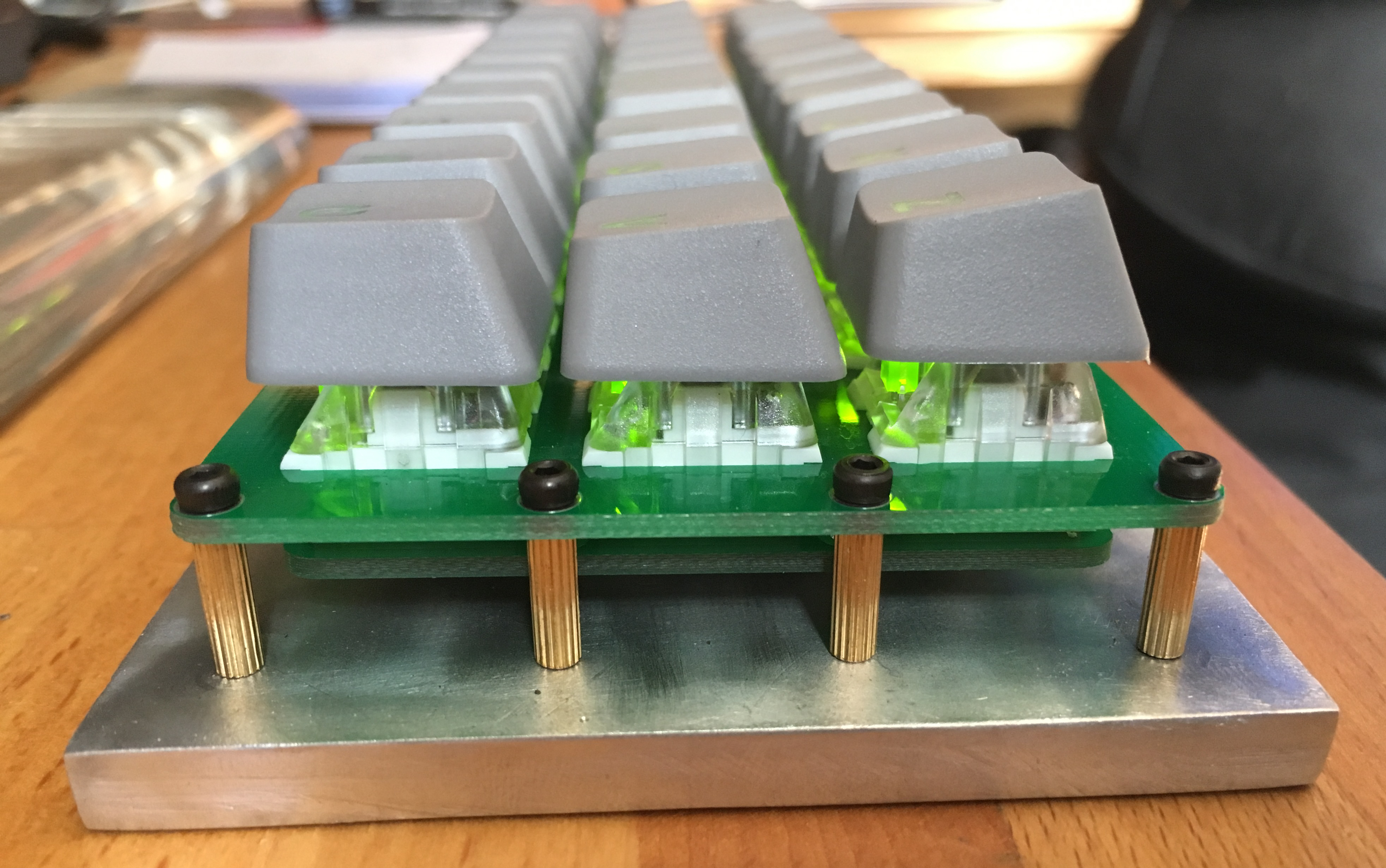
And if you use caps which work with a backlight, it’ll look like this in the dark!
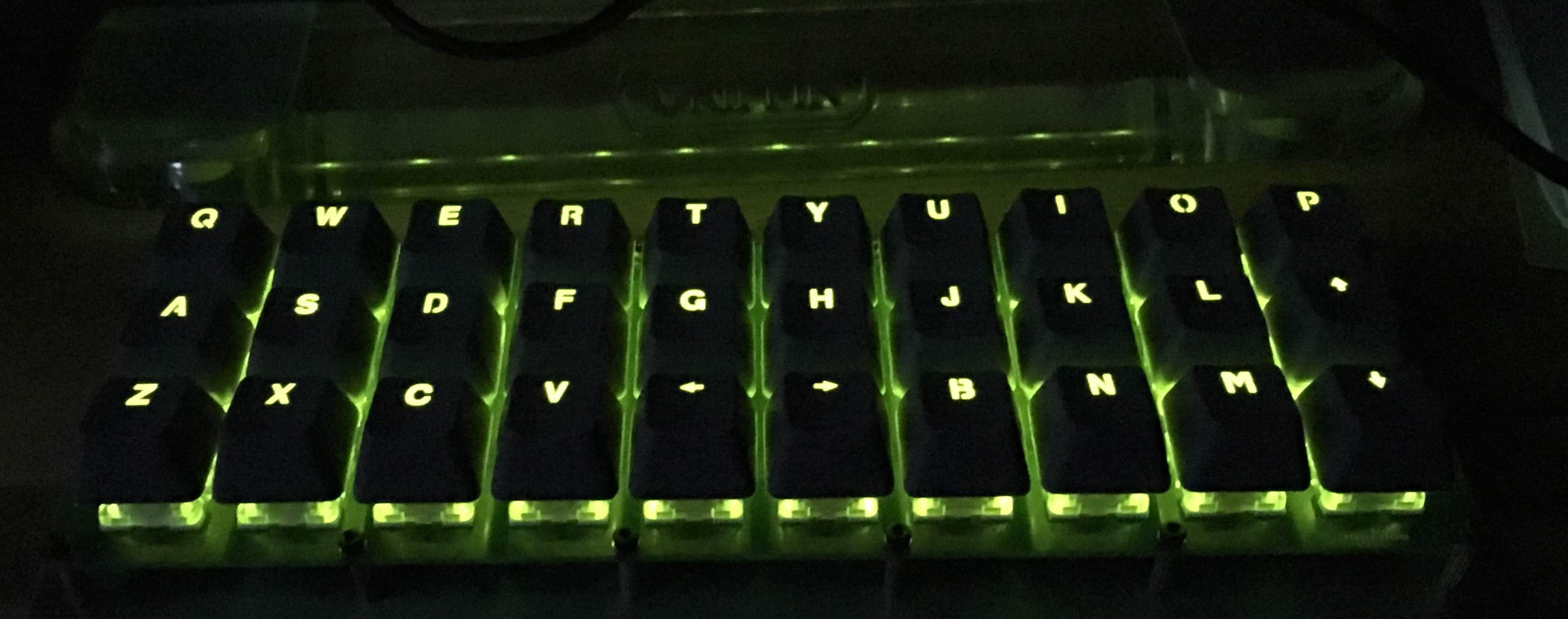
Gherkin with backlight
Wrapping up
I had great fun building my two Gherkins, although to be honest I think I’d prefer a slightly larger ortholinear board, with punctuation on the top layer the very least, so I think that will be my next project.
Hopefully there’s some useful information in here which will compliment the many other builds guides you might find online.