Repairing an MFJ-974 ATU
Apr 23, 2018Last year I decided to finally investigate amateur radio – something I’ve been
aware of and thinking about since I was a child – and got a UK intermediate
license in Jan 2018. I have a couple of handhold radios, but my main interest is
in data modes (there’s another post I’m saving for later).
At the moment, my main antenna is a 25 metre
ladder fed dipole which I threw up so I’d have something to play with. I
didn’t really measure it and so it’s not really resonant on any useful amateur
bands (except about 24 MHz). Like many people with this type of antenna, to
turn my big wire into something workable I use an ATU (antenna tuner unit). ATUs
work by matching the impedance of your antenna system to the impedance of your
radio, optimising power transfer and letting you transmit without blowing your
radio up or causing its level control circuits to reduce your transmit power to
nothing. Unfortunately, in March 2018, my ATU (an
MFJ-974HB balanced line tuner)
died, so I was forced to mend it. Luckily for me, this turned out to be a
fairly simple task. This post documents the process on the off-chance it might
be useful to someone else. Information sharing is a big part of amateur radio, so
I hope this is useful to someone.
Symptoms
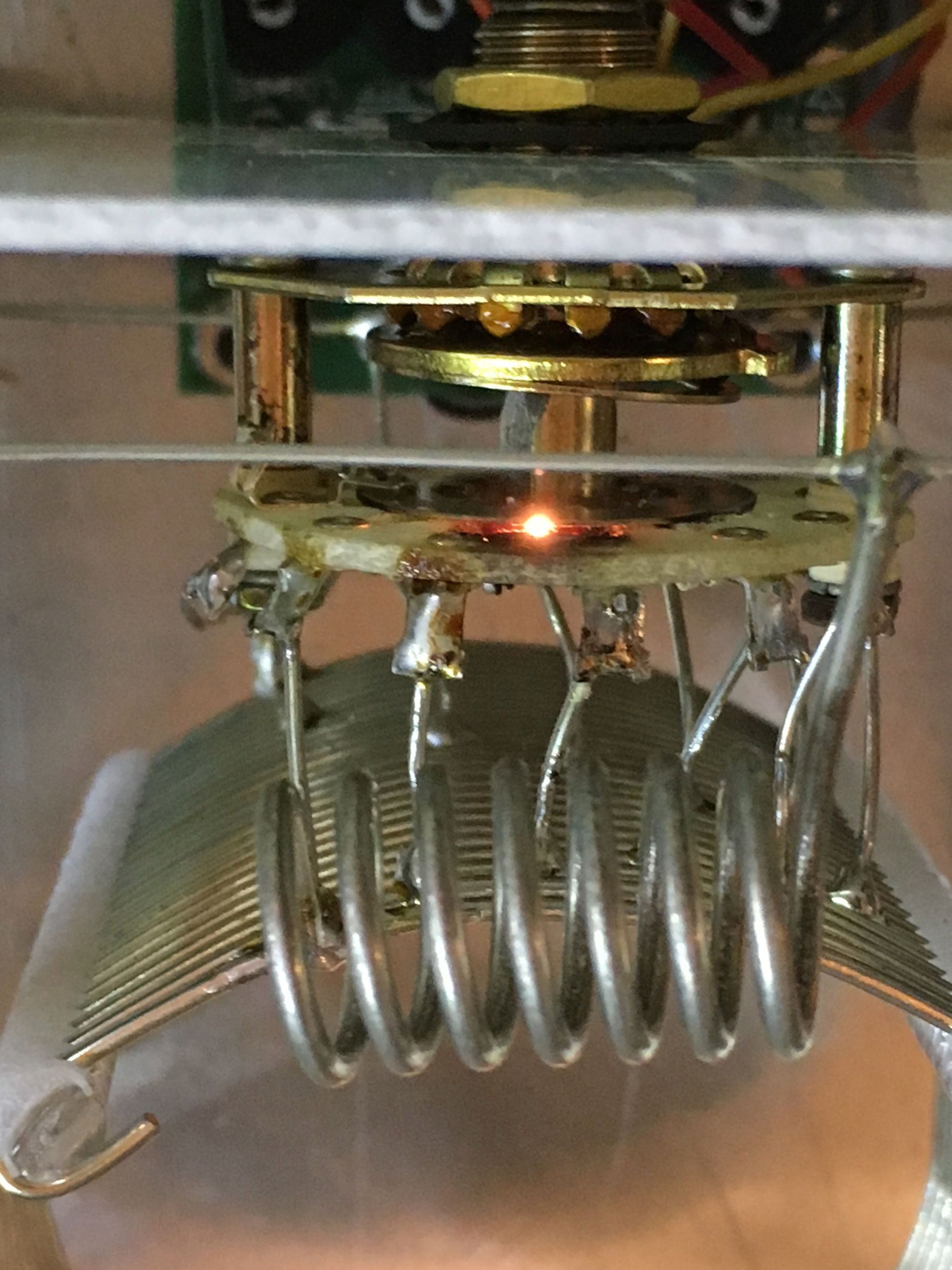
During a particularly windy evening I was playing with WSJT-X FT-8 (don’t judge until you’ve tried it, it’s addictive and harder than you think to get decent DX contacts with simple gear – but that’s another story), when I noticed that as I tried to tune up the SWR meter’s needles were bouncing about and there was a faint glow behind the panel. I was totally unable to get a usable match, and I realised that the glow was probably arcing behind the front panel so I took the cover off to have a look and found a burn mark on the top of the rear wafer part of the inductor’s rotary switch.

When I keyed up the transmitter the arc appeared fairly repeatably at all but tiny power settings, and I suspect that the burned PCB material forming the wafer was conducting quite readily where it had burned. After looking at the rest of the components and finding nothing else awry I figured I would need to replace the rotary switch.
This could have been caused by me trying to change the inductance while tuning, or it could have just been bad luck. I suspect the former, but I don’t recall ever actually doing it! A quick google suggests that this is a common failure mode for this sort of gear, and there’s a lot of negative sentiment towards MFJ as a manufacturer.
Innards
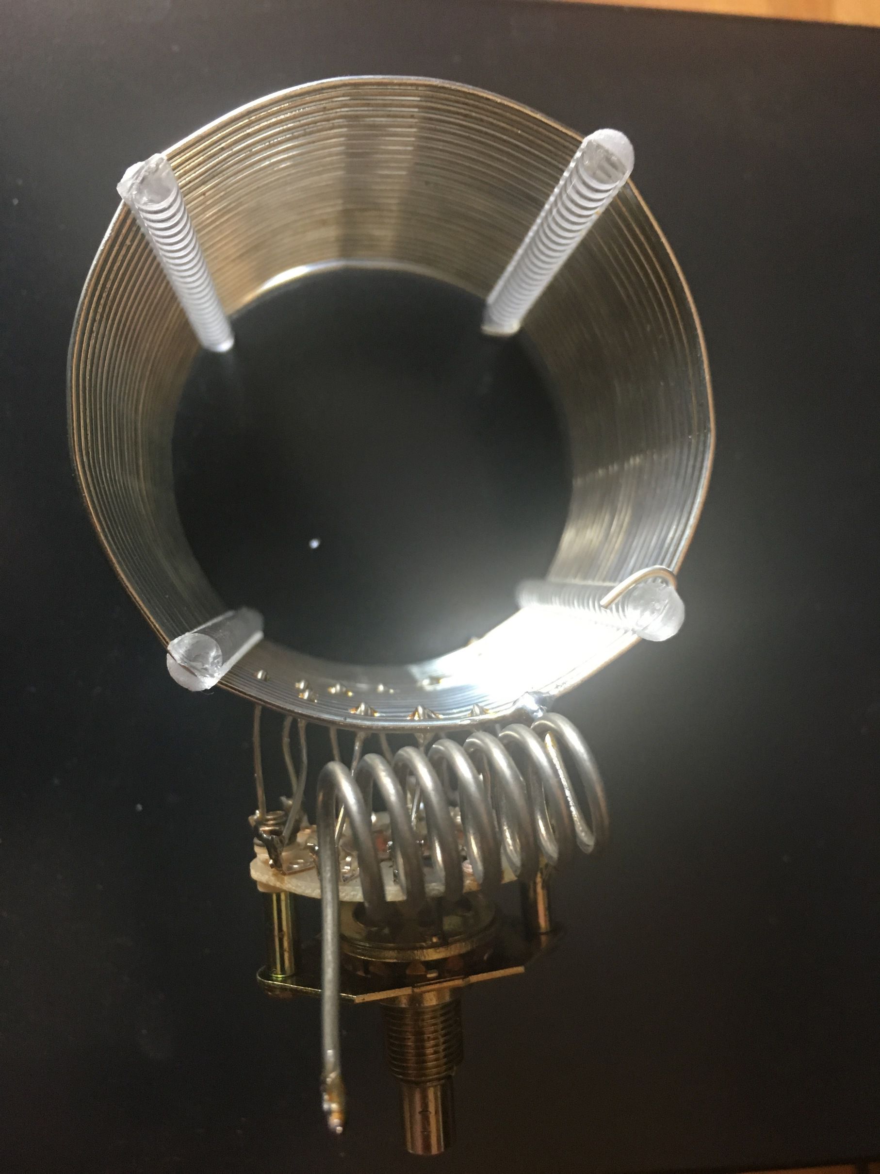
Inside, an ATU is a fairly simple beast consisting of some really big variable capacitors and a really big coil. Cheaper units (like this one) tend to have a coil with multiple taps which are connected to a big rotary switch and larger units tend to have a roller inductor which lets you vary the inductance continuously so doesn’t need the rotary switch. Electronic tuners like you get inside transceivers or on the base of antennas have banks of fixed inductors and capacitors which they switch between using relays, and people who are really serious about reducing losses use resonant antennas which don’t need tuning!
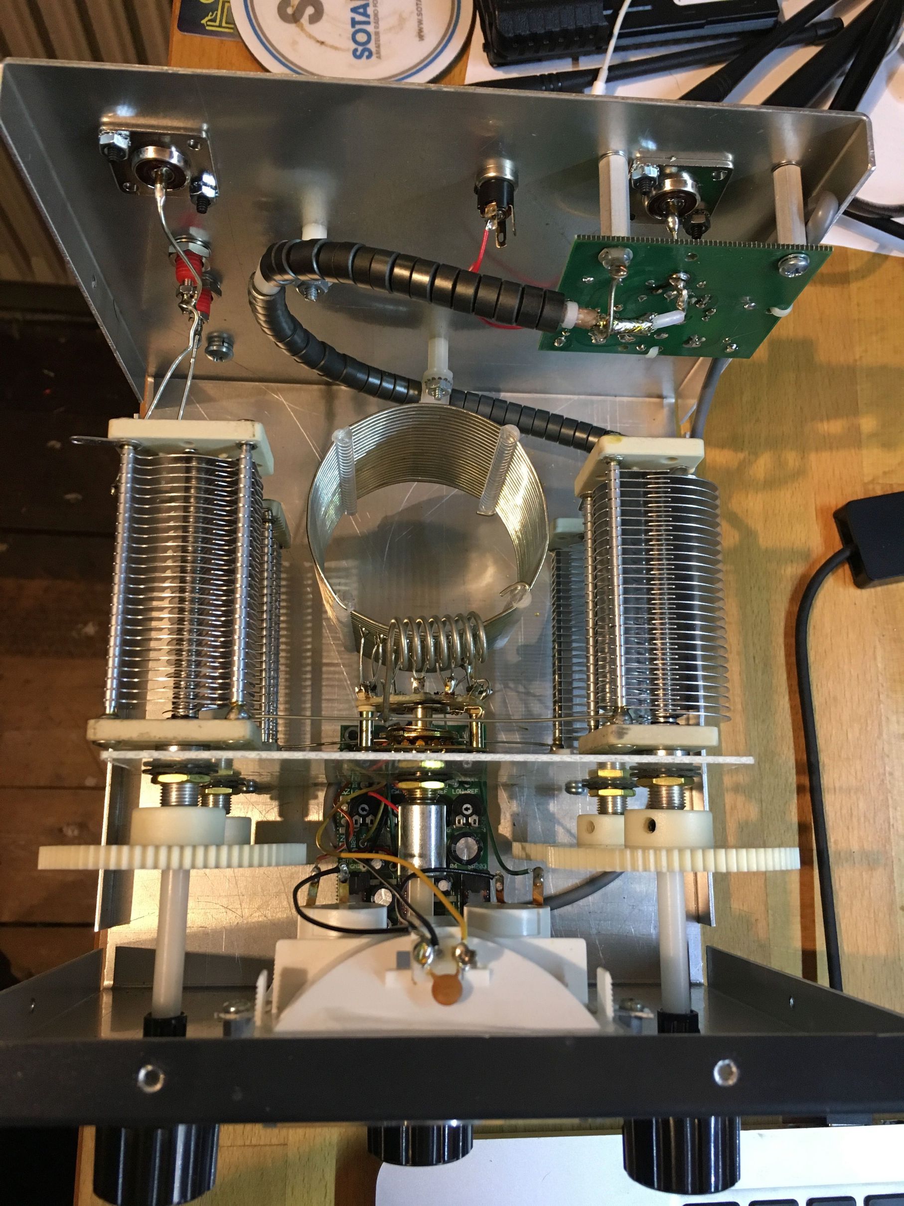
Balanced ATUs are pretty much symmetrical, and are really quite pretty, in this image you can see the two capacitor banks on the left and right, the inductor in the middle and the circuitry for the SWR meter on the bottom. The faulty rotary switch is in the middle, on the panel side of the coil. Finally there’s also a balun on the transmitter side of the unit to convert the unbalanced coax input from the transmitter to the lovely symmetrical inside of the ATU and any connected ladder line. Overall, my ATU feels like it was built very well, using decent components. The main let-downs are probably the nylon cogs and the rotary switch, all of which are fit for purpose in my opinion. Even the rotary switch lasted from 2005 to 2018 without incident.
Parts (and modifying them)
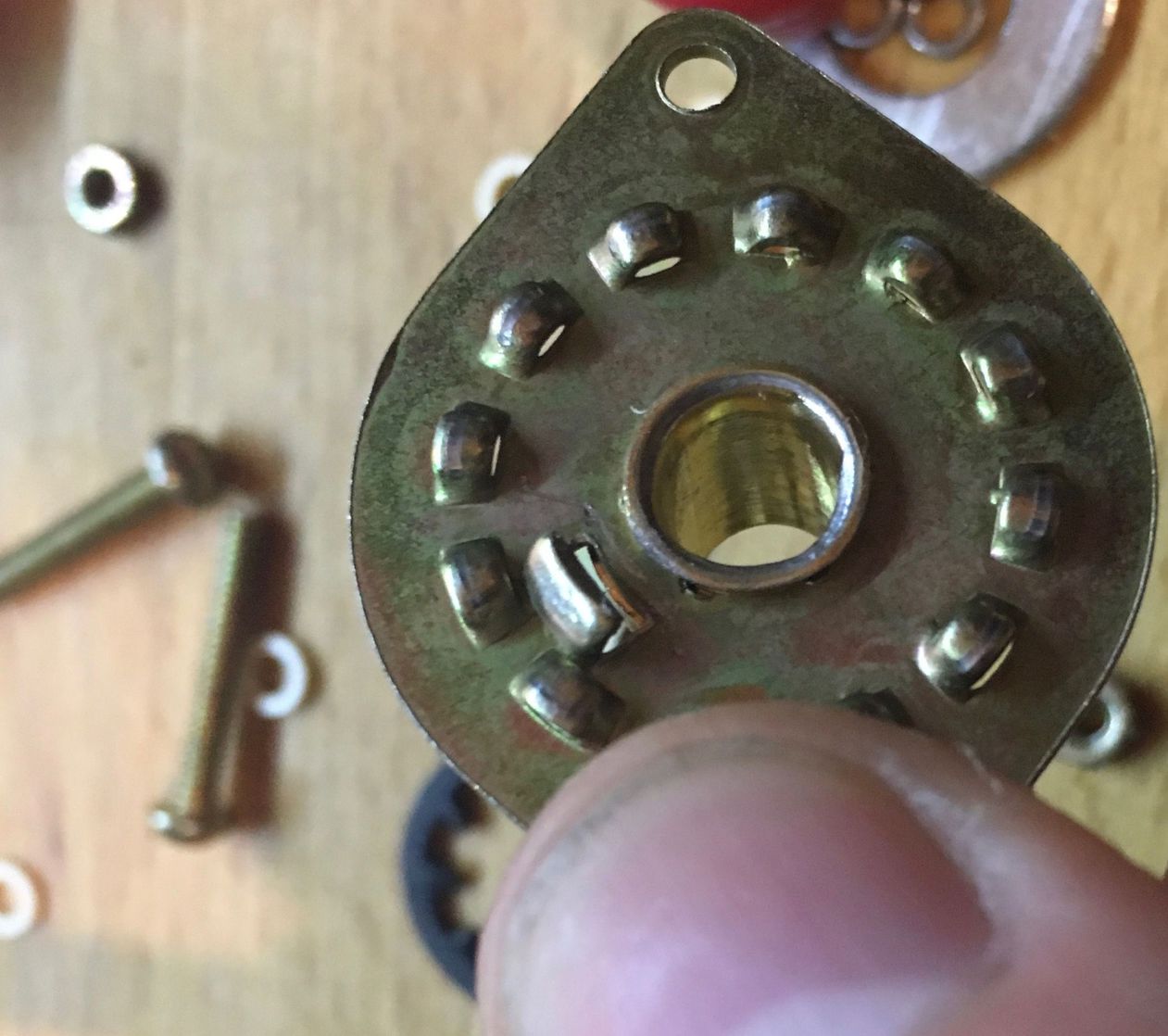
The damaged rotary switch is a single pole device which switches between 12
positions (labelled A to L). Each of these corresponds to a tab on the back
part of the switch (the wafer), and each tab is connected to a different tap on
the coil. The L tab is connected to the base of the coil, which is also the
common tab on the switch, and the A tab is connected to the top. This mean
that in the L position the switch is effectively connected to the bottom of
the coil twice.
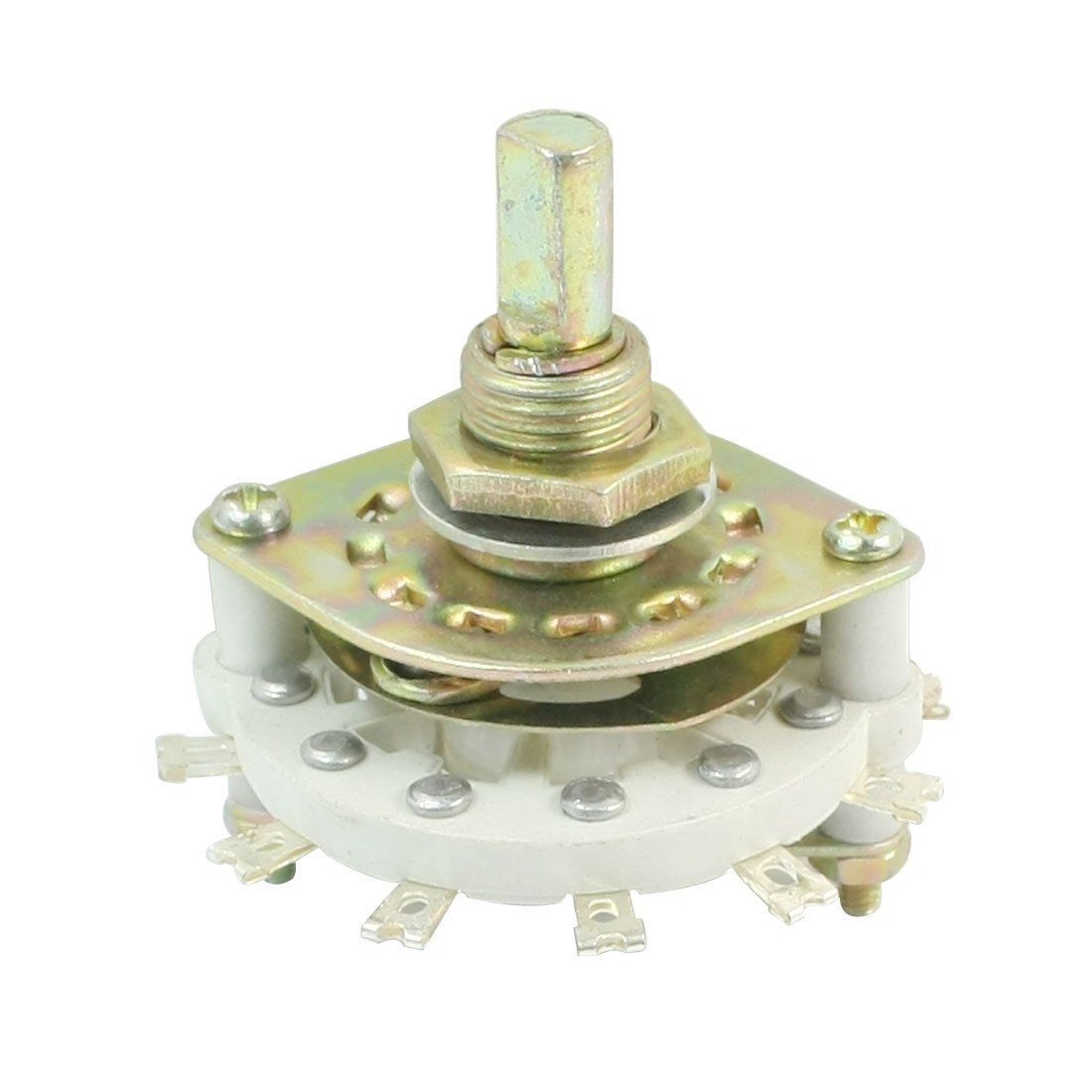
I looked on the RS and Farnell websites for suitable replacements and an absolute top quality perfect item was about £40, which was a good bit more than I wanted to spend. Instead, I went for something I found on eBay, which was marked ‘1P11T’, aka 1 pole and 11 taps or positions. That sounded a bit wrong, but it looked right, so I grabbed one regardless. It was £4, so a low risk.
When the switch arrived I had a quick look at it, it looked like exactly what I
wanted, so I proceeded to swap it into the ATU. However, when I then tested it
I found that one position, the L was physically blocked so couldn’t be used.
Essentially the switch didn’t allow you to set it to a short-circuit, which seems
reasonable I think(!) but in this case is something we actually need.
To solve this issue, I ended up modifying the switch mechanism, by:
- Removing the nuts from the bottom of the two screws, and taking them and all of the bits and pieces out.
- Carefully separating the top mechanism and wafer, and putting the wafer aside in order to concentrate on the top part.
- Gently easing the circlip off the top of the switch in order to allow the ball race to disconnect from the shaft (while being careful not to lose the balls).
- Using some pliers to remove the inner tab which stops the switch from turning 360 degrees. I just bent it back and forward until it snapped off.
- Reversing the above steps to put it back together.
This should then allow the switch to turn freely and rest on the all important
short-circuit position, and so be ready to install. If you want to check I’m
not talking rubbish above this, the circuit diagram is on page 8 of the instruction
manual.
Connection L is on the very top part of L1.
Fitting the new rotary switch was a simple affair, which surprised me, but it did involve a lot of steps so I’m splitting this into several sections. In the first part, you’ll remove the main inductor and rotary switch from within the ATU, in the second part you’ll swap out the switch, and then finally you’ll put it back together.
Removing the coil and switch
By the end of this stage you’ll have removed the very middle of the ATU. That is, the main coil and rotary switch. This part is fiddly, but not complicated.
- First, remove the screws holding the top panel in place, there are 8 in all, two on top and three on each side. The remove the top.
- Next, remove the outside (capacitance) knobs by using a
5/64"hex key to loosen the grub screws opposite the indicator lines. Then take the knobs off. I didn’t try metric hex keys because MFJ is an American company. - Now, turn the unit over and undo the two larger screws from the base. These connect the large white square of PCB material to the base. These two screws have flat bases (no self tapping spikes). Flip the unit back over carefully.
- Use a
7/64"hex key to loosen the black grub screw holding the nylon shaft to the rotary switch, then pull the knob and extension forward to disconnect it from the switch. - Now, take a hot soldering iron and solder sucker and disconnect the two tinned wire sections from the banana plugs on the back. This should leave the four large capacitors, big white square and coil assembly free to move back and forward.
- Gently ease these (the capacitors and coils with their PCB) out of the box so you can get to the top and bottom by rotating it. You could remove the coax from the capacitors if necessary, but I left it in place.
- Now desolder the wires from which connect the two capacitors to the coil and switch. There are two (top and bottom) the bottom one may be looped over the capacitor wire, so use a sucker and pliers to remove it.
- For the last part of this stage, loosen the nut holding the rotary switch in place to allow the coils and switch to be pulled out of the back of the PCB and free from the capacitors.
This should leave you with the coil and switch nicely disconnected from the rest of the unit and ready for switch replacement!
Replacing the switch
In this next stage you are going to remove the old switch and replace it with the new one.
To do this, use a hot soldering iron and solder sucker to gradually remove all of the solder from the tabs on the switch’s wafer. This might take a while, but you should be able to get it to a state where you can pull the switch from the coil fairly easily.
There’s a lot of solder on some of the contacts, so if you have a station you can turn up then I would recommend doing that.
Now, it’s time to switch the switch.
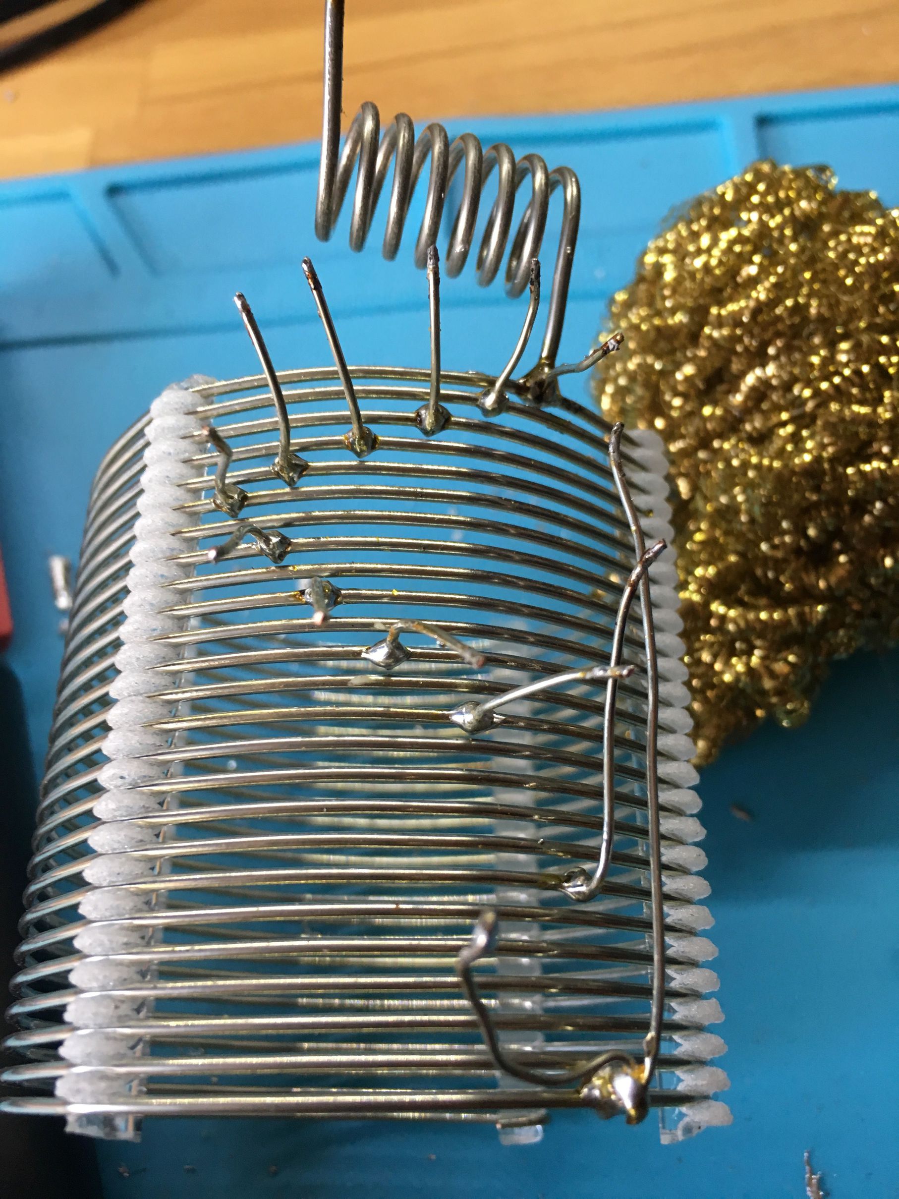
Replacing the switch is similarly simple. Place the wafer in the same
orientation as the old one, and route the wires from the inductor through the
holes. The contact which goes to the bottom of the coil should go to the “main”
contact (this is L on the ATU). This will either be the one you couldn’t
actually switch to if you bought an 11 position switch, or it might have
connection on both sides of the wafer. The orientation of my switch was the
same as the original. You will need to work out which is the main contact of
the switch and install it in the correct orientation if you want the labels on
the ATU to be correct (which clearly you do!).
After inserting all 12 wires into the switch and making sure everything looks level, solder everything back together using plenty of solder. The wafer on my replacement switch was plastic, so I had to be careful not to accidentally touch it with the iron, if you went all out and bought a really good switch then yours might be ceramic instead.
Re-assembly and testing
Finally, it’s time to put the thing back together and check it works. To do this, reverse the steps I gave above, but note that this time you might need to trim the nylon shaft extension which connects to the rotary switch.
When fitting the knobs onto the capacitors it is worth knowing that the
capacitors are at their 0 positions when the vanes are totally overlapping.
You can easily rotate the vanes by hand to put them into position before you
replace their knobs.
Another thing to note is that when you replace the knobs you should not put them too close to the chassis of the ATU as they’ll rub on the front.
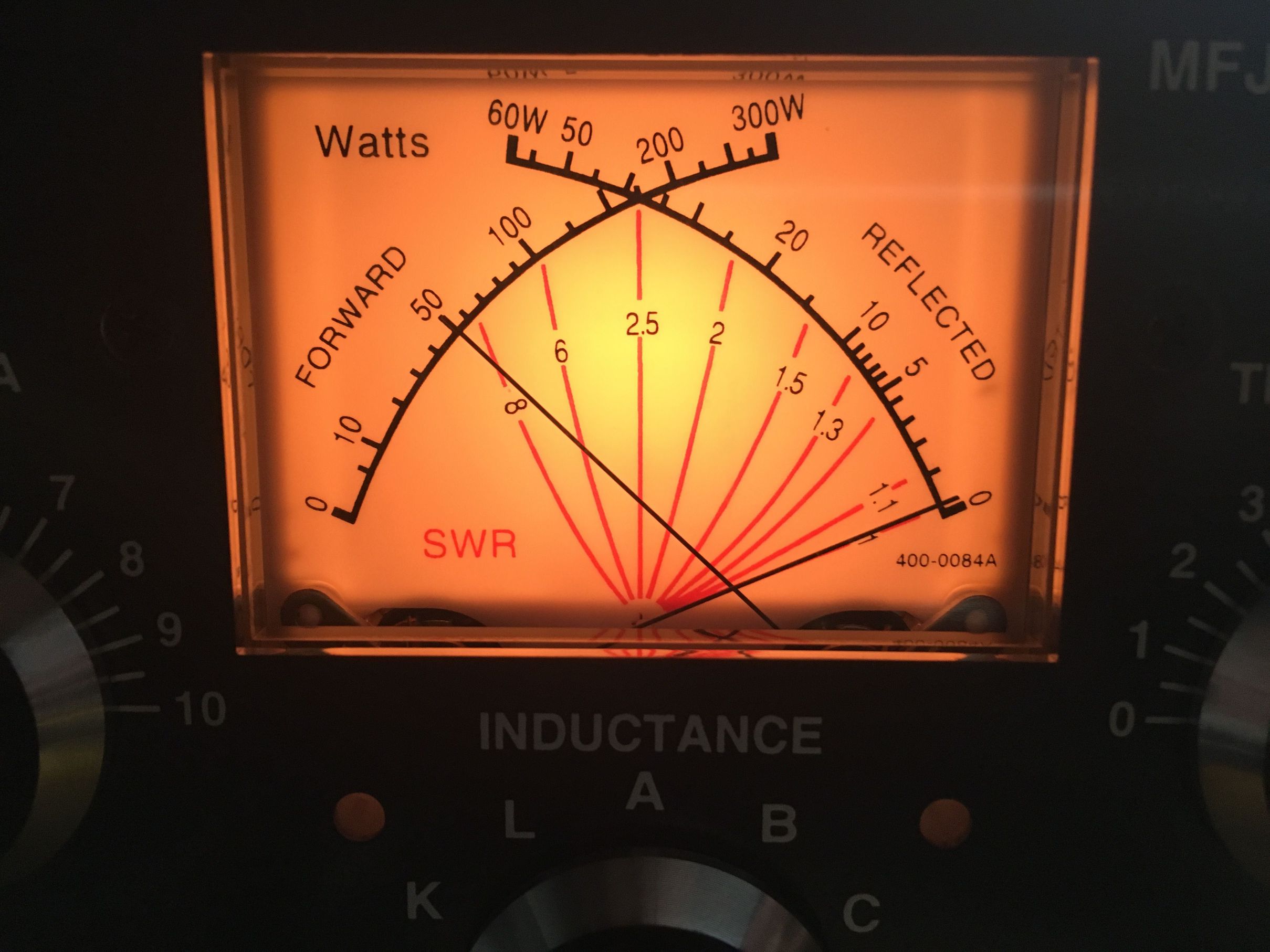
Once you have tightened everything up and checked everything is back together you can test the ATU works as before. To start with, I dropped my rig’s power to the lowest setting possible and connected a dummy load in place of the antenna connection, then I used my rig’s tuning function (which just generates a carrier) to check the ATU still appeared to work. Initially I did this (carefully) with the chassis still open so that I could check nothing obvious was arcing. Next, I repeated the experiment with the antenna instead of the dummy load, and then finally I put the lid back on and screwed it all back together, and did it again. Listening carefully for arcing, I noticed that characteristic fizzing sound, along with the SWR bouncing about again, so I disconnected everything, took the top off again and moved some of the wires on the back of the wafer apart a little. Then, I repeated the above experiments, and finally… Success!
Well, that’s everything. If you’ve read this far hopefully you were repairing your ATU and you found this useful! There are some more images of my repair process online, here.