Christmas Badge Buildathon
Dec 17, 2024Christmas badge buildathon
Like many people, I’m in a small group chat with a silly name and its own weird vernacular. We try to meet up for the BSides London conference each year and have a Christmas party with a ridiculous secret santa and food. In 2023, inspired by badges from infosec conferences like 44con and radio buildathons, I decided to make an electronic badge we could all build and then wear to BSides. The result was a multivibrator circuit with a couple of transistors and four LEDs, which was fun and simple. Naturally, in 2024 I decided to up my game, and I did this by using a microcontroller (MCU) and more LEDs, while incorporating a few tricks I learned by having my friends build the 2023 badge, and keeping the cost per badge below £5.
I don’t do that much tinkering currently, but most of my more recent microcontroller projects have involved messing with STM32 boards and Pi picos (and not actually led to anything useful), but those are expensice and complex, and for this project I wanted something my friends can solder, with an overall low cost, so with that in mind, I decided I’d use Atmel ATTiny45 MCUs, because:
- I’ve used them before.
- I like avr-libc
- They are relatively cheap and small.
- I had some I could play with.
- You can get a through-hole version for noobs.
The group reckoned that 15 or so components was manageable, so I decided to try to pack in as many LEDs as I could. While brainstorming, I remembered there’s a fun sounding technique called Charlieplexing which I’ve been meaning to try, so decided to look into that. Charlieplexing is a way to use tri-state logic ports to control more LEDs than seems possible. Using this method each pair of pins can control two LEDs (one at a time!) but connecting them in parallel, back to back. It’s worth going into this in a bit more detail because it’s a cool technique.
Charlieplexing
Pins in modern MCUs can be set as input or outputs, and when they’re in input mode they have a high impedance which means it’s hard for current to flow through them. In output mode this isn’t the case, and output pins can be set to high (+ve voltage) or low (0v), giving us three pin states.
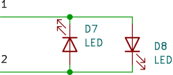
On setting both pins as inputs, the MCU disables the high-impedance (HiZ) mode on the pins allowing current flow. Then, if you set one pin high, current flows from the high pin to the one that’s low. In this circuit, we’ll connect two LEDs, back to back. Then to change which LED is lit, switch the high and low pins (e.g. 1 high, 2 low here will mean D8 is lit). To power everything down we can set the pins as inputs (or leave them both low)

LEDs connected to two ports
This is pretty simple for just two pins, but as I said before, you can control two LEDs with each pair of pins, and that’s where the tri-state logic is useful.
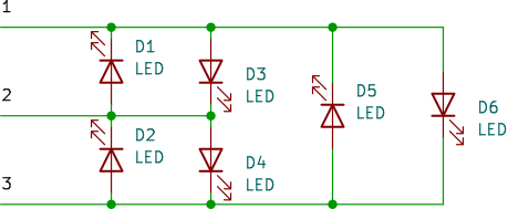
In a three pin set-up you can control 6 LEDs, like this:

LEDs connected to three ports
If you wanted to enable the rightmost LED (D6), you’d set pin 1 high, pin 3 low, and pin 2 to HiZ (by setting it as an input). If you didn’t do that, then D3 would also light up (which is pretty interesting in itself, but I decided not to go into exactly what combinations I could use).
By Charlieplexing five pins on an ATTiny45 I could control up to 20 LEDs (too many!), so I stuck to 12. I did some experiments on a breadboard and determined that I could just about get away without adding any current limiting resistors, meaning that I could probably use 12 LEDs, the chip, a battery holder, and then a switch for good measure, leading to a really low component count.
With all this in mind, and using my breadboarded circuit to double-check details, I drew the circuit in kicad. Finally, I assigned footprints to all the components, using the intersection of “cheap on mouser”, “has a footprint in kicad already” and preferring compenents I’ve used before as my guide.

The full circuit
PCB
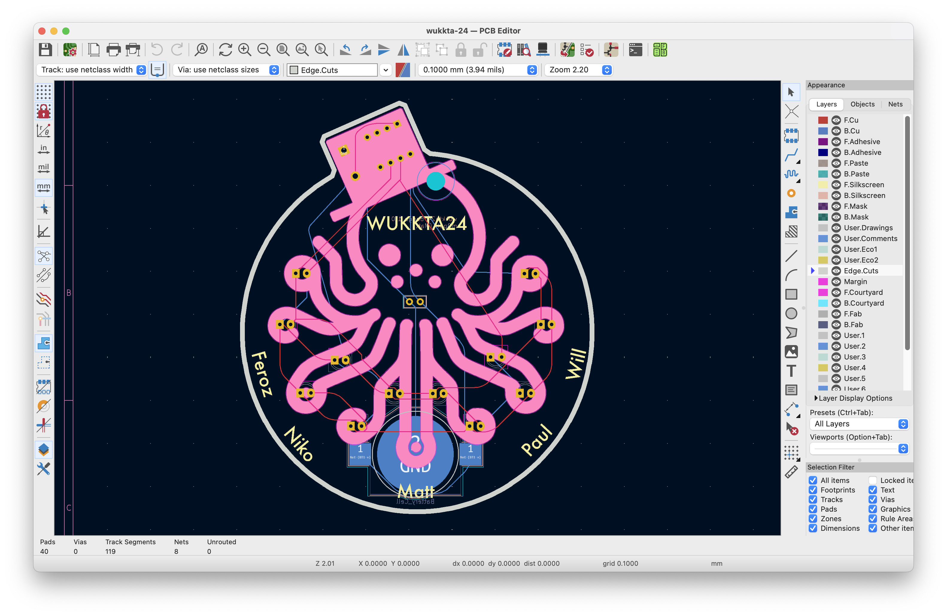
With the circuit drawn it mess about in PcbNew, (kicad’s board layout tool) and route my PCB. I started by importing this repo of JLCPCB design rules into my project (honestly I have no idea if this worked because I forgot to check) and started thinking about my design. For reasons I wanted to use an octopus design ChatGPT made me, but I also wanted it Christmassy. I settled on a bauble shape with LEDs down my octopus’ arms. I added a top-hat to my octopus, also for reasons, and drew a basic design in inkscape (which I find oddly hard to use). The idea here is that the board works as a badge which can clip on a conference lanyard but also converts to a handy Christmas ornament, reducing uselessness (🧠).

KiCad’s PCB editor
This was a nice simple circuit, so routing was only medium-faff. I made all the LEDs face in the same direction for simplicity and fitted the MCU and switch side by side in the hat. Next, I added holes for an optional capacitor which can sit on the back of the board (just in case my friends want something to push the badge away from their chests – the cut-off component legs can catch on clothes). I kept the LEDs symmetrical, and also edited the footprints to increase the size of the pads to make soldering easier (the transistors on the 2023 badges were hard to solder, and I often find small footprints in kits a pain)ki. The final result looked pretty cool in the 3D view, so I bought a bunch in blue from JLCPCB… worried because the crazy edge cuts didn’t show in their viewer… and waited. Thankfully when they arrived they looked great, and initial tests suggested no mistakes! Total cost for 15 boards was $38.86 including fairly speedy shipping.

3D render
Code
The last part of this project was writing code to generate cool patterns of lights and I spent ages messing with this!
First, I wanted to use the button to switch mode, but I had forgotten that not all pins on the MCU are attached to the same internal components. Like a fool I managed to connect my switch to the reset pin which is generally used for… resetting it. I messed about with various ideas (you can disable the reset functionality at the expense of easily reprogramming the chip, and I thought about making a second PCB design using a different pin) but ultimately decided to live with my bad decision. Unfortunately I learned a lot about interrupts and other fun things here, but they weren’t all that useful! What was useful was learning about sleep modes (more on that in a bit).
I spent a bit of time messing with timing and worked out how to make it look like all LEDs were on at the same time, and also made various patterns of running and flashing lights. This is all hard to explain, so I’ll embed a video.
I settled on a series of different flashing patterns which runs through several times after the device powers on, and then, as I mentioned above, the device goes to sleep. In sleep mode the MCU draws very little current, and can either be awoken by an interrupt on one specific pin, or by resetting it. And lucky for me, I have a reset switch. So the end result is a bauble/badge which runs through a series of patterns before basically powering off until the button is pressed.
Conclusions
I was chuffed with this project. People seem to like making badges and there are a few things you can do to make them easier to make and wear. I’d encourage anyone interested in having a go to see what corners they can cut, resistors they can drop, pads they can expand, cheap components they can find and what they can mount on the back of the board to keep the sharp bits off clothes!
You can find all the design files in GitHub, some instructions on my file dump and a cool interactive BOM there too (from a kicad plugin).
Final bill of materials (BOM):
Which gives a total cost of just under £2.50 per board, plus the PCBs at around £2 per board (I bought 15).
