PCB Toaster
Nov 13, 2021This week I completed the electronics rite of passage that is converting a cheap toaster oven into a PCB reflow device. It was a simple and fun project and I can see why it’s such a popular thing to do, and so far I haven’t burned my house down! 🔥 Total cost was about £40, but I think you could do it for less if you shopped around. Of course you shouldn’t try this at home if you plan to blame me for any issues!
Background
Ever since I was at uni I’ve been aware of modified toaster ovens being used to reflow PCBs but until now I’ve not really thought about trying it myself. This changed recently when I decided to learn how to use KiCad, and I ended up designing a board for the bidirectional matched TIA which I keep hearing about in radio homebrew circles. I picked this as a project after watching w2aew’s video on them, and deciding it would be a fun thing to use to play with some test gear.
I ended up making a couple of board iterations, due to some small footprint mistakes, and because of that I now have a lot of cheap boards from JLCPCB. Of course this made me think about speeding up manufacture for no other reasons than I love to automate things, and I used 1608 footprints, so most of the parts are 1.6 by 0.8 mm in size. As it happens, both versions have some annoying footprint problems, but nothing insurmountable, in the second version I accidentally used a tiny pin header, but the rest is fine:
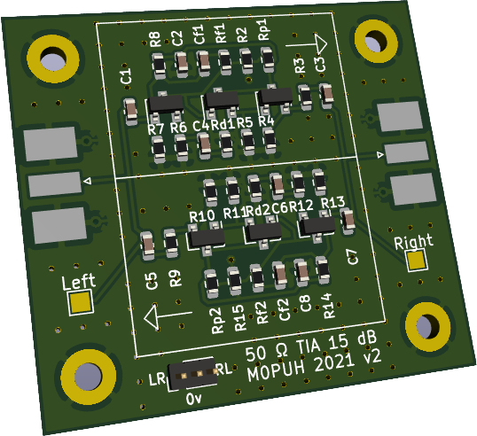
A 3D view of my TIA board. This is version 2.
After a bit of searching, I bought the cheapest toaster oven I could find on eBay. This was a refurbised 650 Watt 9 Litre model, made by Netta, with a clockwork timer and analogue temperature switch. I think almost anything would work if it’s cheap enough to not have any electronics inside.
Next, I looked for temperature controllers and while I was wowed by hundreds of cool projects with LCDs and temperature profiles I decided to keep it simple and bought a cheap PID controller, again from eBay. This came with a thermocouple and a chunky solid state relay. The controller is a REX-C100 (clone).
With those two things I was ready to burn the lab down. I mean build the PCB reflow machine.
Experimentation and construction
The insides of the toaster oven were really simple. There was a small bulb, a clockwork timer switch and a small thermostatic switch which I think works with a bimetallic strip (suggesting the enclosure behind the switch gets hot… which it does). These were connected by wires sheathed with flame retardant tubing, and followed by wires going to the elements. I ripped the timer and thermostat out, but left the bulb in place, then connected the solid state relay where those had been.
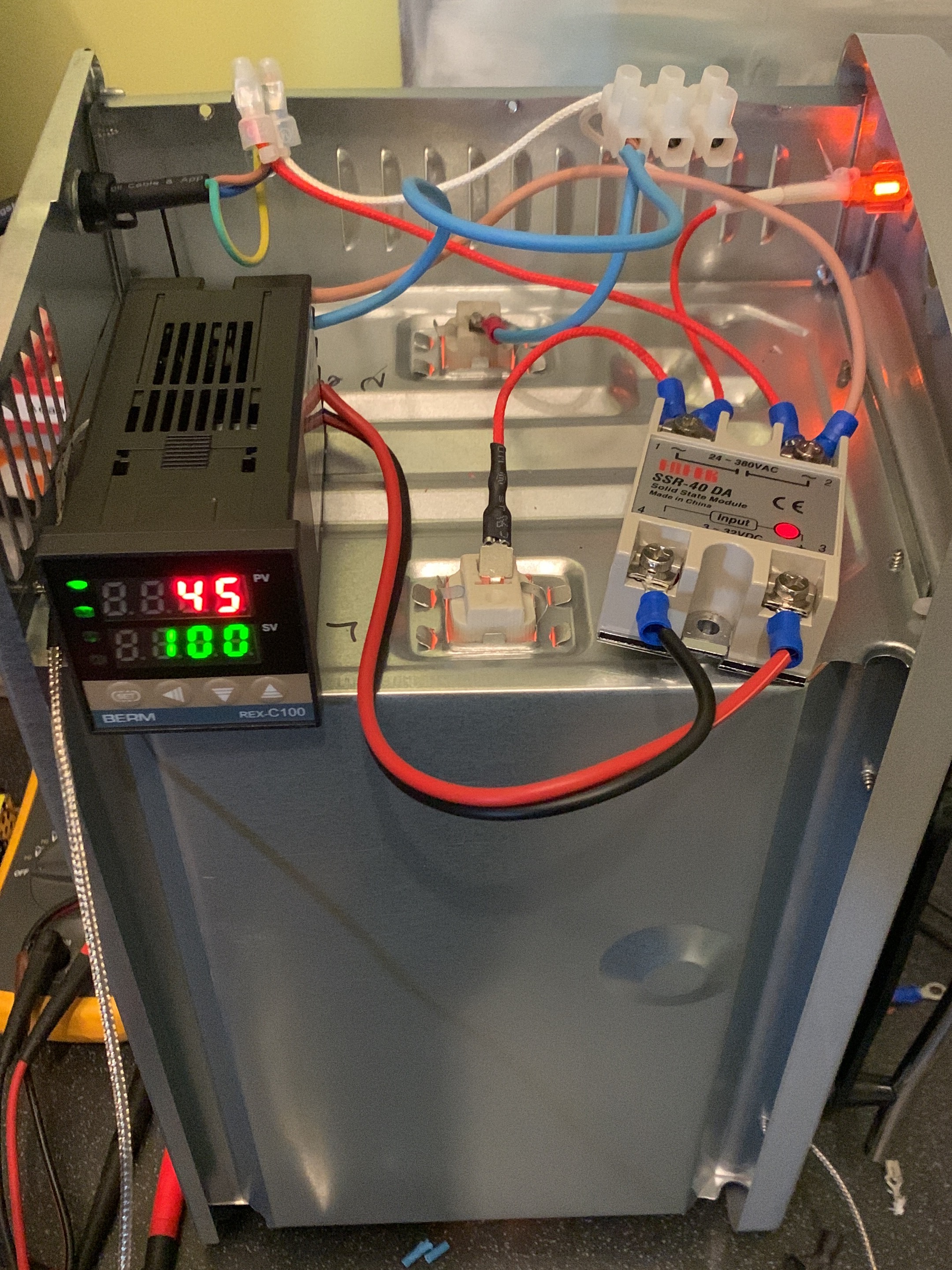
The side of the toaster oven, showing the PID controller and relay
Then, after some tests to make sure the thing worked as I thought (it did), I wired in the PID controller. This had well labeled terminals so was pretty easy to wire in. Then I did some quick tests to see how hot the thing could get (which I clearly should have done earlier), and found it could easily get to around 300 C, which is plenty! I also checked the PID controller worked as I expected and found that it did, but that the thermocouple it comes with lags the temperature of the unit by quite a lot, presumably because of its thermal mass.
Finally, with my plan tested and validated, I use snips to cut a hole in the front of the panel and pushed the PID controller through before neatening everything up (and holding it away from the hot side as much as possible) and putting the lid on.
The moment of truth
With the working device now safely covered up and horizontal it was time to bake a delicious PCB.
I used a tube of maker paste and a BBQ skewer to drop components and pasted onto one of my TIA boards. I built version one of the PCB as a test, and the process was complicated by the relatively large nozzle on the paste tube. I ended up using cotton buds to clean up as I went along and by the time the board was laid out it was a mess. I was entirely sure the result would be awful, but decided to see what would happen anyway!
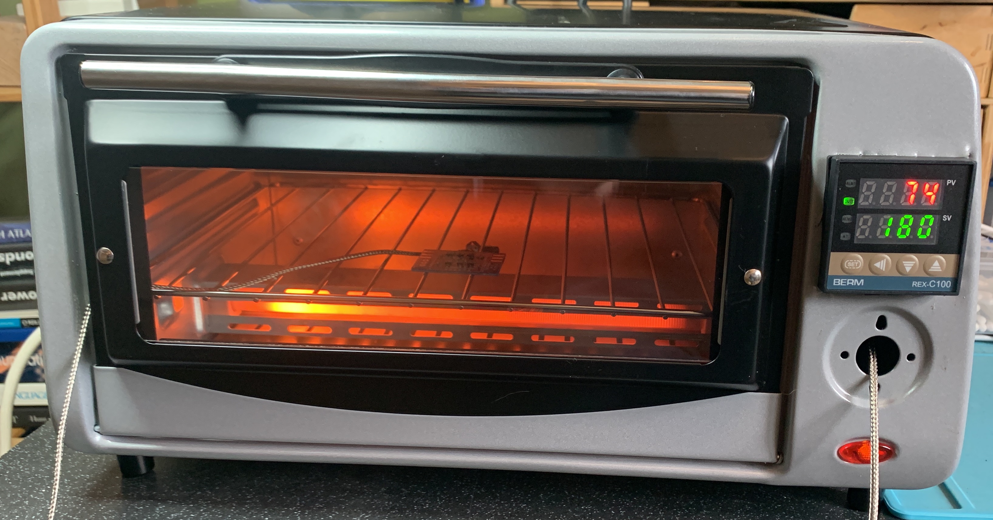
Reflowing a PCB
I set the PID controller to 180 C and put the board inside (the maker paste reflows at 140 C), then watched and waited… and it worked! The flux visibly evaporated and the solder coalesced, leaving a nicely soldered board, with mess where I applied the paste badly. A couple of capacitors needed to be moved and tacked down, and a few blobs of solder needed cleaning, but on the whole the process worked despite my messy paste application! I used a toothbrush and some isopropanol to clean the board when it was cool, and checked the joints, then I powered it up and attached my ‘scope to see if the board worked, and it did!
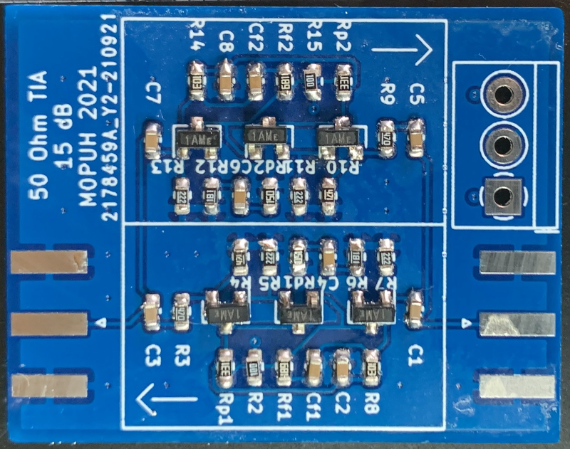
Finished reflowed and then touched up circuit board. Not pretty but not bad.
Conclusions
This was a fun and simple project. There’s mains voltage and a potential for fire, so it’s not necessarily super safe, but I’m glad I did it and I feel like this might be a useful tool. I’m also keeping an extinguisher nearby! 🧯
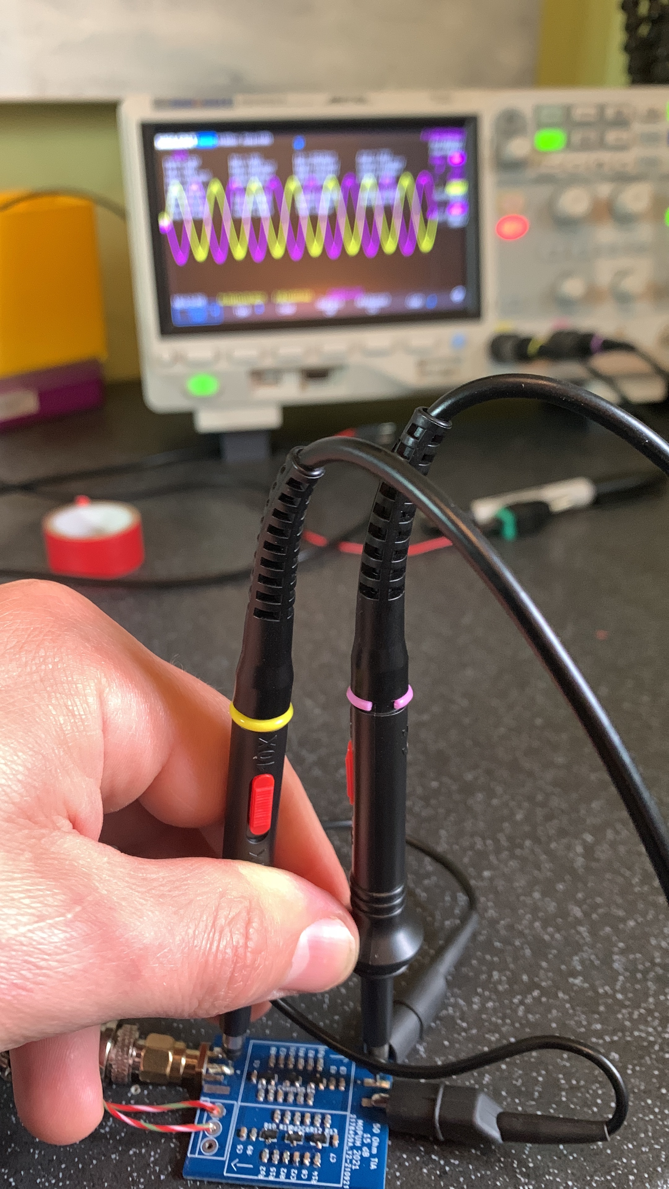
The circuit under test
I might need add a fan to the side of the enclosure where I mounted the relay and PID controller, especially if it looks like it’s starting to melt, but that’s unlikely given how fast reflowing boards is. To do that I’d drill holes in the side/top cover and use a small PC fan.
If I really get into making loads of PCBs I might invest in a more intelligent controller, or look at using an ESP32 (or something) and relay to allow for PC control using MQTT (Tasmota might make this pretty easy).
By far the most frustrating thing was applying the solder paste, and because of that I ordered this great looking solder dispenser (more info here. I’m looking forward to that arriving so I can try it, and hoping brexit means I don’t get lots of import fees (😠 brexit).