Digirig + FT818ND with WSJT-X
Apr 24, 2021Back in January 2021, KN4LIA tooted about the digirig, a single-box data connection for ham radios, being developed by Denis KW0X. I was intrigued and decided to join the mailing list, then decided to buy one of the first batch when they became available. I made my order on the 29th March, and received it on the 7th April, which is not bad for post from the USA! I was eager to give it a go with my Yaesu FT-818ND, so as soon as I got time I made up some cables. Here’s how I did that and my first impressions after using it with WSJT-X.
The main attraction for me was replacing a chunky bundle of cables with one tiny box and three small cables! I’ve never really done any portable operating, but this looks like a way way to get myself ready.
Unboxing
The digirig arrived in a standard jiffy bag, with a small anti-static bag wrapping the digirig inside. This was totally adequate for the compact device, which is about 43 mm by 25 mm square, and packaged in a rugged black extruded aluiminium case. Tacticool is an appropriate term. There’s a micro USB connection on one end and two TRS sockets on the other.
To check it worked I plugged the unit into Raspberry Pi I use for radio stuff
and had a quick look at dmesg. Everything was detected: it shows up as a
CM108 audio controller and a Cygnal CP210x UART:
Bus 001 Device 007: ID 10c4:ea60 Cygnal Integrated Products, Inc. CP2102/CP2109 UART Bridge Controller [CP210x family]
Bus 001 Device 006: ID 0d8c:013c C-Media Electronics, Inc. CM108 Audio Controller
and looking under /dev, I found:
./serial/by-id/usb-Silicon_Labs_CP2102N_USB_to_UART_Bridge_Controller_48eb59d7ba57eb118418ff58fdb0f8d5-if00-port0
Which won’t change if the order of plugged-in USB devices differs so will be handy later.
Inside it looked like all the pics on the website:
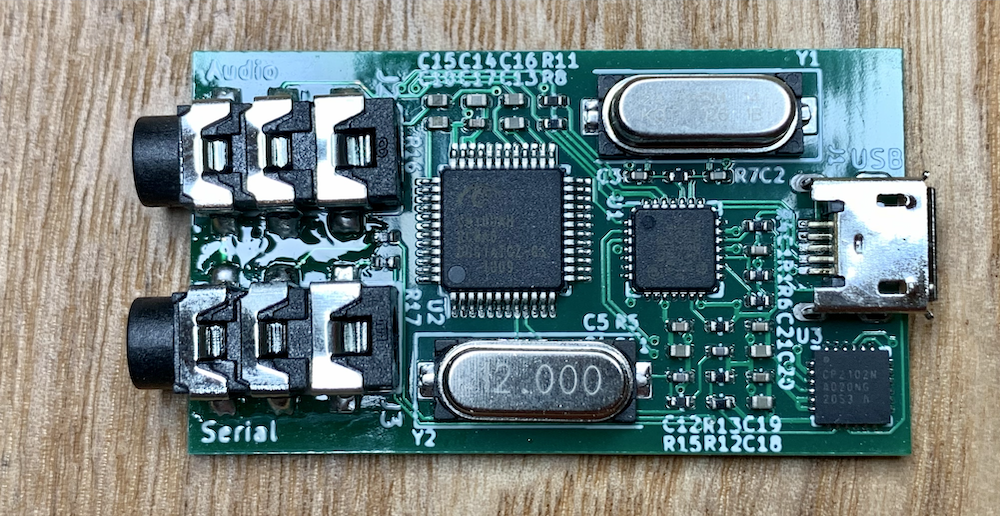
Inside the digirig
Not really the sort of thing you’d want to build at home. The CP2102N chip on the bottom right looks like it might not be too fun to solder!
Connections
I bought the unit without any cables, expecting to build my own (and I knew I had some plugs already). So I had to do a bit of research into pinouts and then whip up a couple of appropriate adapter cables. I’ve been using my iPad to take notes recently, and I ended up with the following (blurgh, I have terrible handwriting):
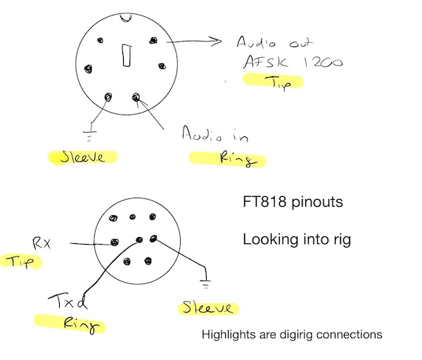
FT-818ND cable pinouts. Check the manual for more detail.
The highlights show how the TRS (tip, ring, sleeve aka headphone) plugs connect to the rig, as described on the digirig site. There are some better images on the digirig site, which I found while I was still writing this post.
To make my cables, I chopped a normal stereo audio cable in half, used a meter’s continuity mode to work out which pin was attached to each wire, then soldered the wires into the DIN plugs. I almost melted the serial plug (the lower one in the image above) so take care when soldering. Alternatively, buy some pre-wired cables and just attach TRS plugs, as they are easy to solder and made of metal so won’t melt(!). After quickly checking for continuity and shorts I plugged the cables into the rig and digirig, then connected it to my Pi and fired up a clean copy of WSJT-X1.
Configuring WSJT-X
WSJT-X lets us use FT8, FT4, WSPR and some other exciting data modes. It also bundles a recent version of hamlib (the most popular software for CAT control) and so tends to work well where other packages might not. CAT means “computer aided transceiver”, and is usually done with proprietary serial protocols that differ for each manufacturer, so having up to date software is useful. As well as that, with almost every radio operator using it all the time the stability and quality are excellent. If you’re new to WSJT-X there’s no substitute to reading the user guide and taking a little time to understand it before diving it.
Configuring WSJT-X can be “fun”, or it can be really easy. I’ve written before about how I did this with my Icom 706MKII, and the process is essentially the same here, with a couple of exceptions.
Working out the settings to use is fairly straight forward, first, look in
/dev/serial/by-id for the CP2102, and use this in the serial port pox.
pi@raspberrypi:/dev $ ls /dev/serial/by-id/
usb-Silicon_Labs_CP2102N_USB_to_UART_Bridge_Controller_48eb59d7ba57eb118418ff58fdb0f8d5-if00-port0
The FT-818ND supports CAT controlled PTT (push to talk), so set that appropriately. Incidentally, I hadn’t noticed that was even a thing and had been using a dedicated serial to PTT box. Cool!
To work out the baud rate for CAT, check the radio’s menu by holding F and turning
the left knob until you get to entry 14 (CAT RATE), then use the value from
there in the drop down, and leave the other settings at their defaults. If you
have problems you could lower this on the radio and in the setting menu.
Finally, in the audio tab you’ll want set both the Input and Output fields to
plughw:CARD=Device,DEV=0, assuming you have no other external audio devices,
then set up your call sign and reporting settings as normal. With that, you should
be done and you get get playing.
And finally… in use
Well, there’s no a lot to say here. It works exactly as advertised. I’ve been playing with 2m FT8 and not had a lot of luck, but that’s my fault, I keep missing everyone by not paying attention and my antenna is too low!
Overall, this is a great value and compact way to connect your rig and computer and I definitely prefer it to my previous setup.
I might add a USB isolator, like the digirig store sells, and I’ll probably rebuild my serial cable with a nicer (less melted) connector but I have nothing bad to say about this.
For rigs without CAT controlled PTT it would be cool to have an extra line available, but that’s not an issue for the FT818.
-
A better alternative would be a clean configuration profile, but I had a clean install ready. ↩︎