TinyAlarm - a simple ATTiny45 based alarm
Oct 14, 2011The TinyAlarm came about because my brother needed a simple alarm for his drum practice garage - something which will scare someone away, but not go off all night, as he doesn’t live near it.
I decided to use an ATTiny45 chip as I had some spare, and thought it was high time I wrote some proper (non-arduino) microcontroller code. Naturally, I decided to use avr-gcc (and friends!).
Programming microcontrollers is mostly a matter of manipulating registers; having the correct datasheet for the device you’re using is absolutely essential, and knowing a little about bitwise arithmetic is very useful. Finally, if you’re using avr-gcc/avr-libc, you’ll need to know C – my C is rusty and rarely exercised, but I think it’s passable!
Behaviour
The behaviour I decided on can be summed up as follows:
- On power up, beep for a while, but don’t go off.
- When triggered, beep for a while before going off.
- If warnings are allowed, check the input after the initial beep before going off.
- Only go off for a short time, and light an indicator LED once the alarm has gone off.
- If multiple alarms are allowed, ensure there’s a wait before going off again.
- And don’t go off too many times!
As well as that, I wanted the system to keep its power usage low, by sleeping as much as possible. In order to do that, I decided to base as much of the system functionality as possible based on interrupts.
Interrupts
Interrupts are events which are triggered by the hardware, and have attached code. In this case, I used them to monitor the alarm’s input (PCINT0), and generate a useful clock signal (WDIE) without having to use one of the devices timer units.
To generate the clock signal, I used the system’s watchdog timer (WDT), and configured it to generate an interrupt every 0.5 seconds. Using the WDT instead of one of the system timers give a lot of flexibility when you want fairly long time period interrupts, as it’s clocked internally at 128Khz, rather than using the much faster system clock. To set up the WDT for 0.5 s intervals, I used:
WDTCR = (1<<WDP2) | (1<<WDP0); /* Set the timeout to 0.5s */
WDTCR |= (1<<WDIE);            /* Enable the interrupt    */
Then defined the code I wanted to run using the ISR (interrupt service routine) macro:
ISR(WDT_vect) { ... }
It’s not possible to pass arguments to the ISR, so you may need to define some global volatile variables to help you keep track of state. It’s also a bad idea to use delays within interrupt handlers, so it’s more usual to count the number of times the handler has been triggered and use that instead. It also has the advantage of leaving the MCU free to do other things when the interrupts aren’t currently firing.
Debouncing
I decided to use a hardware debouncing circuit, to remove the need for any delays in my interrupt handlers. Debouncers are essentially low pass filters, designed to filter out all the dirty signals caused by bouncing switch contacts. I decided to use a fairly standard debouncing circuit with a diode thrown in for extra protection - you can find a really good article on debouncing switches at: http://www.ganssle.com/debouncing.htm.
Alerting
Rather than allow the MCU to power the alarm siren, I opted to use a very simple transistor switch. The main advantage of this is that I’m powering the circuit from a 9 volt battery, via a regulator, so using a switch allows me to use the whole 9v for the siren, instead of the regulated 5v supply used by the chip.
Schematic and Code
Putting all this together leads to a fairly simple circuit, so using schematic capture software doesn’t add much. That said, I’ve been playing with open source EDA software, so ended up drawing it in gEDA. I uploaded both versions of the schematic to github, along with the code. Feel free to use this as you see fit.

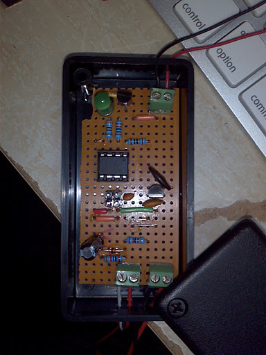
Construction
I built myself a TinyAlarm using veroboard and a small plastic siren from maplin. Veroboard is not pretty, and it can be surprisingly difficult to squeeze circuits onto. I recommend using squared paper and a pencil!